


Published on Nov 30, 2023
A tunable micro-electromechanical systems integrated inductor with a large-displacement electro-thermal actuator is discussed here. Based on a transformer configuration, the inductance of a spiral inductor is tuned by controlling the relative position of a magnetically coupled short-circuited loop.
Theoretical studies are backed by a variety of fabricated and measured tunable inductors that show a 2 : 1 inductance tuning ratio over a wide frequency range of approximately 25 GHz. In addition, the maximum and minimum quality factors of the tunable inductor are measured to be 26 and 10 which is high compared to previous designs. They can considerably extend the tuning capabilities of critical reconfigurable circuits such as tunable impedance matching circuits, phase shifters voltage controlled oscillators, and low noise amplifiers
The operating principle of the presented tunable inductor can be explained on the basis of an integrated transformer configuration, as shown in Fig. 1. The primary coil is the coil whose inductance needs to be controlled. The secondary coil is short circuited and magnetically coupled to the primary one. The magnetic flux linkage between the coils induces eddy currents in the secondary coil. When the magnetic coupling between the inductors is changed, the equivalent inductance seen at the primary port is also changed. This is the main concept behind this tuning approach. However, existing studies have only considered the case where the two coils are identical. Here we analyze for the first time the generalized equivalent circuit of two different coils and investigate the associated design methodology to attain an optimal performance. In addition, we perform high-frequency full-wave simulations with Ansoft's High Frequency Structure Simulator (HFSS) and mechanical simulations with ANSYS to predict the performance of the proposed tunable inductor structure Electrothermal Actuator
Electrothermal actuators are used for moving secondary short circuit loop wrt primary because simple fabrication, low actuation volts, lack of pull in instability.
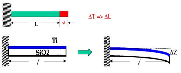
. It composed of two bimorph (Ti/SiO2)actuator arms anchored on substrate.
. These arms support the short circuited secondary inductor.
. Applied voltage between two anchors induces a current flow on Ti layer resulting in Joules heating and bimorph bends down. It is because of fact that Ti has greater value for the coefficient of thermal expansion than SiO2.
In this tunable inductor, we control the magnetic coupling between the two coils by controlling their relative distance and overlap area. In this technique, a large displacement (>100um) is critical in achieving a significant variation in the magnetic coupling coefficient that leads to a large inductance tuning range. To accomplish a large vertical displacement by MEMS actuation, we adopt an electrothermal actuator due to its simple fabrication process, low actuation voltage, and lack of pull-in instability
In this tunable inductor, we control the magnetic coupling between the two coils by controlling their relative distance and overlap area. In this technique, a large displacement (>100um) is critical in achieving a significant variation in the magnetic coupling coefficient that leads to a large inductance tuning range. To accomplish a large vertical displacement by MEMS actuation, we adopt an electrothermal actuator due to its simple fabrication process, low actuation voltage, and lack of pull-in instability. As shown in Fig. 5, the electrothermal actuator is composed of two biomorph Ti/Si O actuator arms anchored on the substrate. These arms support a thick electroplated gold loop that constitutes the short-circuited secondary inductor. The high thickness for this loop is needed for two reasons, which: 1) results in the lowest possible resistance for the secondary coil and 2) results in a very planar secondary coil despite the fabrication residual stress.
The analysis of this actuator was performed by ANSYS with the material properties listed in Table I. An applied dc voltage between the two anchors induces a current flow on the Ti layer resulting in Joule heating that causes the biomorph beams to bend downwards. This is shown in Fig. 5. Fig. 6 depicts the tip deflection in terms of input power. When 0.13 V is applied at the anchors, the nominal dc resistance and current on the actuator wa =20um and La =200um are 3.7 and 35.1 mA, respectively. Therefore, the tip deflects by 144 m (34% of the total length ) with an input power of 4.6 mW
We considered two different possibilities for the primary 2-D spiral tunable inductor. In the first case (type 1), the primary spiral is printed on the substrate [see Fig. 7(a)], while in the second case (type 2), it is suspended in air anchored on the substrate by two via holes [see Fig. 7(b)]. Type 2 may appear more attractive because of its significantly lower parasitic capacitance to the substrate that results in higher quality factor and self-resonant frequency. On the other hand, it imposes strict requirements on the fabrication process since a very low residual stress is needed to maintain a planar profile that will prevent a direct contact with the suspended secondary inductor. The final choice depends on the maturity of the employed fabrication technology.
The electrothermal actuator presented in Section B moves the short-circuited secondary loop along a curvilinear path. We employed HFSS to model the tuning behavior due to this movement. The simulated inductance and quality factor as a function of the tip height of the short-circuited loop are depicted in Fig. 8. As expected, when the tip height is decreased, the frequency-dependant inductance and quality factor are also decreased. It is also worth noticing the differences between Figs 8(a) and (b). Fig. 8(a) depicts the results of a 4- m-thick Au spiral coupled to a 4- m-thick Au short-circuited loop, while Fig. 8(b) shows the results of the same spiral when coupled to a 0.5- m-thick Ti short-circuited loop (both loops have a 0.5- m-thick SiO layer underneath their metal layer).
The latter figure clearly shows the limited inductance variation at lower frequencies and the rapid degradation of the quality factor as the short-circuited loop deflects downwards. In Section , we demonstrated that the resistance of the loop has a considerable effect on the equivalent resistance and bandwidth of the variable inductance. Thus, these results from HFSS confirm the results of the simple equivalent-circuit model of Fig. 1. The magnetic coupling coefficient k is also extracted from Fig. 8 using (4). As can be seen in Fig. 9, k decreases sharply as the short-circuited loop approaches the spiral, but saturates for large tip heights. Therefore, in an optimal design, the initial deflection caused by the residual stress should be carefully controlled to minimize the actuation power required to move the short-circuited loop close to the spiral.
| Are you interested in this topic.Then mail to us immediately to get the full report.
email :- contactv2@gmail.com |
